L293d Motor Driver Circuit Diagram Pdf
L293D Image: DataSheet: L293D is a dual H-bridge motor driver integrated circuit (IC). Motor drivers act as current amplifiers since they take a low-current control signal and provide a higher-current signal. Keygen generator software. Pin Diagram: Pin Description.

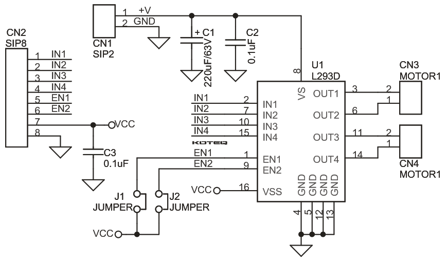
The speed of the DC motor (both directions) is controlled with the 10k potentiometer which is connected to analog channel 0 (A0) and the direction of rotation is controlled with the push button which is connected to pin 8 of the Arduino UNO board. If the button is pressed the motor will change its direction directly. The L293D driver has 2 VCCs: VCC1 is +5V and VCC2 is +12V (same as motor nominal voltage). Pins IN1 and IN2 are the control pins where: IN1 IN2 Function L H Direction 1 H L Direction 2 L L Fast motor stop H H Fast motor stop As shown in the circuit diagram we need only 3 Arduino terminal pins, pin 8 is for the push button which toggles the motor direction of rotation. Pins 9 and 10 are PWM signal outputs, at any time there is only 1 active PWM, this allows us to control the direction as well as the speed by varying the duty cycle of the PWM signal. The active PWM pin decides the motor direction of rotation (one at a time, the other output is logic 0). Arduino code: Arduino code is below.
