Msi Ms 7301 Ver 10 Manual
• MS-7304 (V1.X) Mainboard. • If a problem arises with your system and no solution can be obtained from the user’s manual, please contact your place of purchase or local distributor. Alternatively, please try the following help resources for further guidance.
Vis i t the MSI webs ite at http://glob al.msi. Com.tw /index. Func=faqIndex for FAQ, technical guide, BIOS updates, driver updates, and other information. • Safety Instructions Always read the safety instructions carefully.
Keep this User’s Manual for future reference. Keep this equipment away from humidity. Encore karaoke player v 9 polnuyu versiyu. Lay this equipment on a reliable flat surface before setting it up. The openings on the enclosure are for air convection hence protects the equip- ment from overheating.
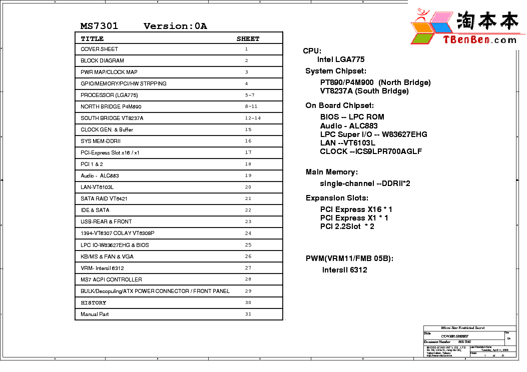
Bios: V0.27 of. Product: Cuba MS-7301. Version: W7301VP2.027 (). Its a MSI CUBA MS-7301, its an OEM motherboard for a Packard Bell Imedia 2470, so there is no support for it on the MSI website.
• FCC-B Radio Frequency Interference Statement T h is eq uip men t h as been tested and found to c omply with the limits for a Class B digital device, pursuant to Part 15 of the FCC Rules. These limits are designed to provide reasonable protection against harmful interference in a residential installation. • WEEE (Waste Electrical and Electronic Equipment) Statement. • CONTENTS Copyright Notice..ii Trademarks..ii Revision History..ii Technical Support..ii Safety Instructions..iii FCC-B Radio Frequency Interference Statement.iv W EEE (Waste Electrical and Electronic Equipment) Statement.v Chapter 1 Getting Started.1-1 Mainboard Specifications.. • Getting Started Chapter 1 Getting Started Thank you for choosing the MS-7304 v1.X Micro-ATX ® mainboard. The MS-7304 is based on AMD RS780 & SB700 chipsets for optimal system efficiency. Designed ® to fit the advanced AMD Athlon64 / Athlon64 X2 / AM2+ processors in Socket AM2/ AM2+, the MS-7304 deliv- ers a high performance and professional desktop plat- form solution.
• M S-7304 M ainboard Mainboard Specifications Proce ssor - Supports AMD Athlon64 / Athlon64 X2 /AM2+ processors - Supports 4-pin CPU fan pinheader with Fan Speed Control - Supports up to 5000+ and above - Hyper Transport supports up to 3.0GHz Chipset - North Bridge: AMD RS780 - South Bridge: AMD SB700. • Getting Started Connectors Back Panel - 1 SPDIF-out port - 1 DVI port - 1 IEEE 1394 port - 6 USB 2.0 ports - 1 Gigabit LAN jack - 6 flexible audio jacks Onboard Connectors - 2 USB 2.0 connectors (4 ports) - 1 IEEE 1394 connector - 1 SPDIF-out connector - 1 front panel connector. • M S-7304 M ainboard Mainboard Layout CPU_FAN1 JSPDO2 DVI Port USB Ports Top: 1394 Port Bottom: USB Ports Top: LAN Jack Bottom: USB Ports Line-In JPW1 AUX_FAN1 Line-Out T: R S-Out RS780 M: CS-Out PCI E1_X1 B: SS-Out BATT PCI E16_X1 CLR_CMOS1 LA N Chip SB700. • Hardware Setup Chapter 2 Hardware Setup This chapter provides you with the information about hardware setup procedures. While doing the installation, be careful in holding the components and follow the installation procedures. For some components, if you install in the wrong orientation, the components will not work properly.
• M S-7304 M ainboard Quick Components Guide JPW1, p.2-8 C P U _ F A N 1, DIMM Slots, p.2-6 A U X _ F A N 1, Back Panel CPU, p.2-3 p.2-12 I/O, p.2-9 ATX1, p.2-8 BATT CLR_CMOS1, PCI Express p.2-16. • If you do not have the heat sink and cooling fan, contact your dealer to purchase and install them before turning on the computer. For the latest information about CPU, please visit php?func=cpuform. Important Overheating Overheating will seriously damage the CPU and system. Download lagu dadali. • M S-7304 M ainboard CPU Installation Procedures for Socket AM2/ AM2+ 1. Please turn off the power and unplug the power cord before Open the lever installing the CPU. Sliding the plate 90 degree 2.
Pull the lever s ideways away from the socket. • Hardware Setup Installing CPU Cooler Set W hen you are installing the CPU, make sure the CPU has a heat sink and a cooling fan attached on the top to prevent overheating. If you do not have the heat sink and cooling fan, contact your dealer to purchase and install them before turning on the computer. • M S-7304 M ainboard Memory These DIMM slots are intended for memory modules.

For more information on compatible components, please visit tw/index.php?func=testreport DDR2 240-pin, 1.8V 56x2=112 pin 64x2=128 pin Dual-Channel Memory Population Rules In Dual-Channel mode, the memory modules can transmit and receive data with two data bus lines simultaneously. • Hardware Setup Installing Memory Modules 1. The memory module has only one notch on the center and will only fit in the right orientation. Insert the memory module vertically into the DIMM slot. Then push it in until the golden finger on the memory module is deeply inserted in the DIMM slot. • M S-7304 M ainboard Power Supply ATX 24-Pin Power Connector: ATX1 This connector allows you to connect an ATX 24-pin power supply. To connect the ATX 24-pin power supply, make sure the plug of the pin 13 power supply is inserted in the proper orientation and the pins are aligned.
