Full Bridge Gate Driver
So each vendors use different malayalam fonts with different keyboard layouts. Malayalam fonts zip file free download.
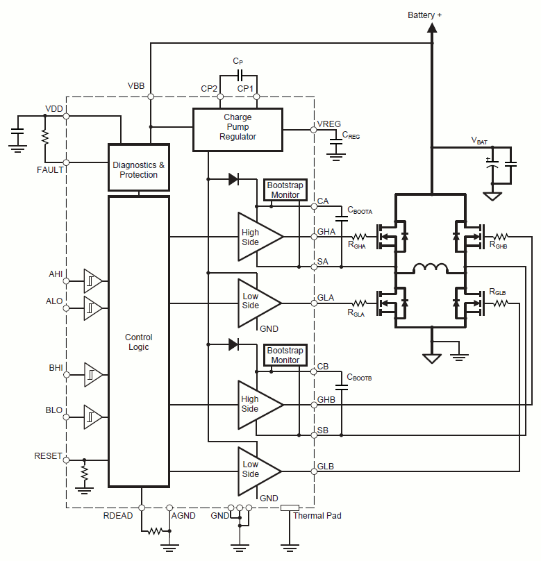
The PWD13F60 is a high-density power driver integrating gate drivers and four N-channel power MOSFETs in dual half bridge configuration. The integrated power MOSFETs have low R DS(on) of 320 mΩ and 600 V drain-source breakdown voltage, while the embedded gate drivers high side can be easily supplied by the integrated bootstrap diode. The high integration of the device allows to efficiently drive loads in a tiny space. The PWD13F60 device accepts a supply voltage (V CC) extending over a wide range and is protected by means of low-voltage UVLO detection on the supply voltage. The input pins extended range allows an easy interfacing with microcontrollers, DSP units or Hall effect sensors.
LM5045 FULL-BRIDGE CONTROLLER WITH INTEGRATED GATE DRIVERS. LM5045 Full-Bridge PWM Controller With Integrated MOSFET Drivers. O High Side Output Driver MOSFET.
The device is available in a compact VFQFPN package. Key Features • Power system-in-package integrating gate drivers and high-voltage power MOSFETs • Low R DS(on) = 320 mΩ • BV DSS = 600 V • Suitable for operating as • Full bridge • Dual independent half bridges • Wide driver supply voltage down to 6.5 V • UVLO protection on supply voltage • 3.3 V to 15 V compatible inputs with hysteresis and pull-down • Interlocking function to prevent cross conduction • Internal bootstrap diode • Outputs in phase with inputs • Very compact and simplified layout • Flexible, easy and fast design Circuit Diagram.
Structure of an H bridge (highlighted in red) H bridges are available as, or can be built from. The term H bridge is derived from the typical graphical representation of such a circuit. An H bridge is built with four switches (solid-state or mechanical). When the switches S1 and S4 (according to the first figure) are closed (and S2 and S3 are open) a positive voltage will be applied across the motor. By opening S1 and S4 switches and closing S2 and S3 switches, this voltage is reversed, allowing reverse operation of the motor. Using the nomenclature above, the switches S1 and S2 should never be closed at the same time, as this would cause a short circuit on the input voltage source. The same applies to the switches S3 and S4.
This condition is known as shoot-through. Operation [ ]. The two basic states of an H bridge The H-bridge arrangement is generally used to reverse the polarity/direction of the motor, but can also be used to 'brake' the motor, where the motor comes to a sudden stop, as the motor's terminals are shorted, or to let the motor 'free run' to a stop, as the motor is effectively disconnected from the circuit. The following table summarises operation, with S1-S4 corresponding to the diagram above. S1 S2 S3 S4 Result 1 0 0 1 Motor moves right 0 1 1 0 Motor moves left 0 0 0 0 Motor coasts 1 0 0 0 Motor coasts 0 1 0 0 Motor coasts 0 0 1 0 Motor coasts 0 0 0 1 Motor coasts 0 1 0 1 Motor brakes 1 0 1 0 Motor brakes 1 1 0 0 Short circuit 0 0 1 1 Short circuit 0 1 1 1 Short circuit 1 0 1 1 Short circuit 1 1 0 1 Short circuit 1 1 1 0 Short circuit 1 1 1 1 Short circuit Construction [ ].